One of the problems Ive seen that users of ex-military Clansman radio have, is that of inadvertently leaving the set on, and ending up with a flat battery.
Clearly, in its original role, the radio would rarely be unattended. Either an operator would have it on his back and be wearing 'phones, or it would be in a position where the low battery alert (breaking of the squelch three times a second) would be heard.
Not so in amateur use. Besides, in amateur use, its unlikely that any other form of power indication, a light for instance, would cause any hassle, as it might under battle conditions. So, it seems sensible to look at the possibility of providing these radios with a 'Power On' indication.
Electrically, such a thing is about the simplest circuit you can think of! An LED, a series resistor, and a source of power that is constant when the set is switched on. Physically, this could be a challenge! It will involve finding a suitable place on the case of the radio to drill a small hole and mount the LED. It also requires finding where the connection can be made.
Although the PRC-350 is likely to be the easiest of the radios to add a power LED to physically, I dont have the service manuals and EMERs to hand for it! But I do have them for the PRC-351, so have had a look...
There are several supply lines in the PRC-351 - 3v, 6v, 9v, 17v and 100v. The 3v and 6v lines seem likely to be quite sensitive, and the 17v and 100v too high. So the 9v line would seem to be the supply of choice. I dont want it to take too much current though, but limiting the current to much less than the LED manufacturer specifies will only result in a dimmer light, which is likely to be preferable anyway. Ideally, a low current 3mm LED would be used, to minimise the loading.
I suspect that a usable brightness can be had from a modern 3mm red LED for very little forward current, but I will rig one up on the bench with a 9v supply and a potentiometer and find an acceptable brightness, then measure the pot to find what series resistor is needed.
On the PRC-351, the main source of the 9v line is module 19 pin 3. But, this line can also be found on several other modules - 20 pin 23 (DC switching), 13 pin 10 (Tx AF), 7 pin 9 (Rx AF) and 8 pin 2 (Non linear amp). Which to select would be the one that is nearest to the LEDs position!
I do need to open my -351 up at some point to perform the L/W volume mod described earlier in this blog (to make the Tx modulation level the same in both settings), and to finally add the rubber boot to the 10m conversion switch, so will look at adding a power LED at the same time.
Tuesday, 13 June 2017
Monday, 12 June 2017
T4 class AB bias - sorted?
As I said I would, I replaced the bias resistor R15 (1k8) for T4 with a potentiometer, which just happened to be on the bench and a value of 4k7. Monitoring the base voltage with one eye, and the current drawn with the other, I adjusted the value of this pot. At some high value, the current actually dropped!, but as the resistance was lowered, I hit the point where the transistor would go into thermal runaway, the current climbing, slowly at first then exponentially faster, up to several hundred mA!
Several attempts later, and I hit on a setting where the meter needle stayed put even after watching for longer than it took to start climbing before. Measuring the pot (and the original resistor, they were in series) gave a value of 2800 ohms.
I replaced the pot and original R15 with a 2k7 unit, but this was too low and the current started to climb. A value higher, 3k3, and the current stays where it is on the meter needle, a total circuit current of around 75mA. I had already measured the circuit up to but not including the driver at 60mA, so the Tx driver is now set taking about 15mA. This might still be too high, but at least now seems stable! Ive asked for confirmation and advice on the G-QRP club forum, that ive done the right thing here.
One ZTX327 left - Taking it steady!
The old Marconi RC-690 PA board had one remaining ZTX327 transistor on it. I have very carefully removed this (not easy on public safety grade equipment designed for shock and vibration immunity), taking care to ensure it doesnt get too hot. On my component tester, the freshly removed device reads a base voltage of 723mV and beta 52.
The removed transistor from the transverter reads 714mV and beta 85. Oddly, this read much higher on the first pass, but then stabilised at 85. I suspect that is down to the tester. But, it seems both transistors are functional. The 1N4148 diode in thermal contact also tested out fine. I can only think that the problem is the bias voltage. I shall replace the 1k8 resistor at R15 with a potentiometer and slowly increase the bias, watching the current drawn as it goes.
 |
| Testing... Testing... |
Sunday, 11 June 2017
Transverter Setback
More work this evening on the transverter, after that is, building a clothes prop for Julie's washing line!
I spent some time taking some readings of the various stages using an RF probe and DVM. With the 28MHz drive set at 5dBm (the most I can give it) the input to the SBL-1 mixer measured 147mV (this is the 5dBm IF signal), the oscillator input 114mV, and the mixer output around 2mV. The input to the Tx buffer stage 4mV, and the output 30mV. All well and good. I tuned my MVT-7100 scanner to 70MHz USB and even without defeating the squelch could hear the thing from a good 5m away!
After a lot of searching and enquiring after equivalents, I decided first to use a 2N3866 in place of the specified ZTX327 transistor for the driver amp. I had just two of these. Well, I managed to snap the emitter leg off of the first one! So, I built the stage using the second, but then decided to try and find an equivalent to the MRF237 specified for the PA.
By an odd coincidence, something on the net linked me to the circuit of the Marconi RC-690 PA strip, where I discovered there is an MRF237 - and I have one of these boards! Trouble was, I couldnt find it! So, after tearing the workshop apart I eventually located this PCB - and discovered that there are some ZTX327's on it as well!
Its from here on that it all started to go wrong!
Getting the ZTX327s off of the board was awkward, and when it finally came, a bloody great blob of molten solder fell on my finger! Thats coming up in a nice blister. I removed the 2N3866, which by this time included all the surrounding parts of the driver amp, and rebuilt it using the ZTX327 i'd just removed. On powering up and measuring the output using the RF probe, all looked great, well over 100mV, but now the input measured only a few mV, not the previous 30mV - it seemed to be badly loading the previous stage... and then I started to smell it!
Oh my gawd it was running hot! Incredibly hot! The PSU's meters showed this stage dragging around 250mA. I powered down and had a think. Back to the books and internet for a bit of research, and decided to check the bias was sensible. Disconnecting the drive by desoldering the leg of the trimmer, I measured the DC voltage on the base - 0.68V, hmmm, seems about right to me? But, it kept dropping, quickly to 0.46V then more slowly. And it still got very hot. I tried a blast of freezer spray and it made no difference, and by this time the clean peaks on the spectrum analyser had degenerated into a mass of sproggies!
I suspect ive killed this transistor! But why? Was the bias at fault? Is the 1uH choke too low in value? Or was the transistor already faulty, or damaged in being removed from the PCB? Because im lazy, and im regretting this now, I didnt bother to test it before hand.
Tomorrow, i'll start this stage again. The old PCB has one more ZTX327 to salvage. This time, however, i'll test it before soldering it in!
I spent some time taking some readings of the various stages using an RF probe and DVM. With the 28MHz drive set at 5dBm (the most I can give it) the input to the SBL-1 mixer measured 147mV (this is the 5dBm IF signal), the oscillator input 114mV, and the mixer output around 2mV. The input to the Tx buffer stage 4mV, and the output 30mV. All well and good. I tuned my MVT-7100 scanner to 70MHz USB and even without defeating the squelch could hear the thing from a good 5m away!
After a lot of searching and enquiring after equivalents, I decided first to use a 2N3866 in place of the specified ZTX327 transistor for the driver amp. I had just two of these. Well, I managed to snap the emitter leg off of the first one! So, I built the stage using the second, but then decided to try and find an equivalent to the MRF237 specified for the PA.
 |
| Putting down another pad |
Its from here on that it all started to go wrong!
Getting the ZTX327s off of the board was awkward, and when it finally came, a bloody great blob of molten solder fell on my finger! Thats coming up in a nice blister. I removed the 2N3866, which by this time included all the surrounding parts of the driver amp, and rebuilt it using the ZTX327 i'd just removed. On powering up and measuring the output using the RF probe, all looked great, well over 100mV, but now the input measured only a few mV, not the previous 30mV - it seemed to be badly loading the previous stage... and then I started to smell it!
Oh my gawd it was running hot! Incredibly hot! The PSU's meters showed this stage dragging around 250mA. I powered down and had a think. Back to the books and internet for a bit of research, and decided to check the bias was sensible. Disconnecting the drive by desoldering the leg of the trimmer, I measured the DC voltage on the base - 0.68V, hmmm, seems about right to me? But, it kept dropping, quickly to 0.46V then more slowly. And it still got very hot. I tried a blast of freezer spray and it made no difference, and by this time the clean peaks on the spectrum analyser had degenerated into a mass of sproggies!
I suspect ive killed this transistor! But why? Was the bias at fault? Is the 1uH choke too low in value? Or was the transistor already faulty, or damaged in being removed from the PCB? Because im lazy, and im regretting this now, I didnt bother to test it before hand.
Tomorrow, i'll start this stage again. The old PCB has one more ZTX327 to salvage. This time, however, i'll test it before soldering it in!
Saturday, 10 June 2017
4m Transverter progress
Whilst it was raining this morning, I decided to do a bit more to the transverter. Thanks to members of the G-QRP club forum, I now knew how to arrange the coil L2, which had me puzzled due to its air wound construction and need for a 1t primary. I wasnt sure exactly where to put that turn!
 Winding it was fun! I decided to use red enameled wire for the 1t so I could actually see it! The photo below shows it soldered in position.


With the unit powered, a few checks with the frequency counter were done to check that the oscillator 42MHz was running and appearing in all the right places - particularly the output of the buffer! This done, I fed the mixer with a 28MHz +5dBm signal from my Marconi 2955, and looked for an output
So the mixer is working. 5dBm is a little low for proper testing (around 3mW), and the input to the mixer is designed to be 10dBm (10mW), but 5dBm is the most I can get out of the test set! Next step the pre-driver amp. Another fiddly little 7t air wound coil needed. But, before this, me and Sam had a job to do - run a CAT5e cable to Sams bedroom! This took up most of the day!

In the absence of the specified BF199, ive substituted a 2N3904 in this position. The completed pre-driver section, and the above mentioned, now permanent, resistor chain, can be seen on this photo below. At this stage, getting hungry and it being late, I did a final test, before finishing off for the night.


With this done I could start progressing towards building the amplifier strip, but first I wanted to check how things were doing so far, in particular, the SBL-1 DBM (Double Balanced Mixer, the left hand silver box with legs) and its Dual Gate Mosfet buffer, needed testing. So after adding the first trimmer capacitor, which gave me a convenient point to connect, and tacking on the resistor chain that takes the supply to the buffer (these become permanent later in the amplifier) I set up a simple test.

With the unit powered, a few checks with the frequency counter were done to check that the oscillator 42MHz was running and appearing in all the right places - particularly the output of the buffer! This done, I fed the mixer with a 28MHz +5dBm signal from my Marconi 2955, and looked for an output
So the mixer is working. 5dBm is a little low for proper testing (around 3mW), and the input to the mixer is designed to be 10dBm (10mW), but 5dBm is the most I can get out of the test set! Next step the pre-driver amp. Another fiddly little 7t air wound coil needed. But, before this, me and Sam had a job to do - run a CAT5e cable to Sams bedroom! This took up most of the day!

In the absence of the specified BF199, ive substituted a 2N3904 in this position. The completed pre-driver section, and the above mentioned, now permanent, resistor chain, can be seen on this photo below. At this stage, getting hungry and it being late, I did a final test, before finishing off for the night.

Thursday, 8 June 2017
PRC-350 Volume Control Mod
One of the problems with the Clansman FM radios, the PRC-350 and -351, is that they have just two audio settings - Whisper (W), and Loud (L). When in W mode, the received audio is attenuated by 20dB, in order that the enemy cant hear your radio. But, at the same time, the microphone gain is also increased by 20dB, so that you can whisper and the enemy cant hear you! All well and good under battlefield conditions, but not terribly good for amateur use! Ideally, what we amateurs want is the mic gain, and hence the Tx deviation, to remain the same, and to be able to change the received volume.
So, being on a short shift today, and having done my good deed for the day dealing with a medical emergency, I decided to use my bit of extra free time this evening to sort this issue out.

The PRC-350 opens up by unfastening four captive hex bolts, and then folds out, taking care with the now very old flexi-connections! The bit I wanted to work on is Assembly 12, which is on the section folded out. Five captive screws hold this board into the case, so had to be undone to lift the board out to access the solder side.
From the service manual, I had found that when W mode is selected, this connects pin 9 of Assembly 12, to ground. This is detailed as the 0VW line. Grounding pin 9 selects a bias capacitor that increased the mic gain by 20dB. A similar line works on the audio amp module for receive, but I didnt want to change that

I first tried cutting the track, but it turned out that the pad to the right is just that, probably for an automatic test jig during manufacture, and the flexi-board connection was made via through hole plating.
So, in order to effect the modification, I got the joint nice and hot and removed the solder with a combination of a solder sucker and desoldering braid. After testing the ensure that the pin was indeed disconnected (with W selected you can do a continuity test to ground, there should be a path from the pad but the pin should be open circuit) I then carefully slid a little sleeving over the pin and into the hole, to insulate it. It can just be seen in the above photo. Finally I wrote the mod and the date on the PCB with an indelible pen.
A bit of adjustment of the audio levels, and I now have a PRC-350 that has the same Tx deviation in both modes, but now the L and W controls are simply a volume control.
The same mod, but I expect slightly different, probably in terms of the connections rather than technique, should also be possible with the PRC-351. That will have to wait for another day.
Ive also bought some superglue today, so could do a bit more work on the 4m transverter now I can glue the pads down! Not much more done this evening, just the Tx IF input attenuator, and a test of the changeover relay.

Next stage requires the positioning of an open air wound transformer - 7t secondary with a 1t primary. The problem I have is that im unsure where the primary should be positioned relative to the secondary!
Amendment - Ive had a few moments spare while my tea settles, to look at the service manual for the PRC-351. Exactly the same method is used in the -351 as the -350. In W mode, a connection to the Tx audio module is grounded. As it happens, it is again pin 9, but in the -351 on Assembly 13.
Wednesday, 7 June 2017
Two Projects completed
Managed to get some time in the workshop today to get the Dew Heater Controller and the Clansman PRC-350 Battery Conversion finished. Started with the Dew Heater, this required a lot of wiring up! I also discovered a mistake i'd made, in wiring ALL the connector tags to ground - the Heater outputs needed a common Vcc connection!

Again, liberal use of heatshrink, mostly colour coded. A range of tests carried out as construction progressed, including checking that the Arduinos on-board regulator could handle 13.8V (ive had some blow!), and that the device recognised the temperature sensor on each port. This at first didnt work, but that was because I had wired the sensor chip up to the phono lead backwards! A final check with the temperature sensor, heater band, and a can of freezer spray, showed all to be working properly. All that is left now is to label everything up and put the lid on!
So next up came the LiPo battery for the PRC-350. This wasnt a complicated task, but was difficult! First, another cutout was needed for the switch that will control the external auxiliary outputs. I managed to measure this wrong (or rather, right but in the wrong place) and drilled a 12mm hole then filed it out for the rectangular shape of the rear of the switch. It was only then that I realised that the part of the switch that will actually sit through the panel was round like the front! So I remeasured, and with a very bouncy and complaining step drill bit, expanded the whole to 20mm
A further cutout had to be drilled and filed for the USB charger module. At least there were no surprises in the shape of this! However, this is where it became difficult. I now had to solder and connect various wires inside a very small closed box.


Again, for very obvious reasons of there being essentially a 15V 3A 30C bomb in the box, liberal use of heatshrink was required. I also managed to wire the main switch to the battery terminals directly forgetting to fit the fuse! Another bit of corrective work and the fuse holder, plus 2A fast blow fuse, was connected The battery terminals were then reconnected, and coated in hot melt glue to insulate the screws.
A very liberal sloshing about of hot-melt glue then to secure the low voltage monitor and the USB charger modules in place.

A few bits of foam were inserted then to hold the battery in place and to stop it bouncing about in the box, and the switch, DC jack and USB output tested. So, if required, this pack can provide 5V out from the USB for general use charging phones or running small devices, and 15V up to 2A for other uses. I would anticipate that being used for devices with their own internal regulators!


As can be seen in the above photos, the low voltage monitor comes into play when the shorting plug is attached. I do still need to attach a lanyard to this to the battery case to avoid it being lost. The battery is also now marked, like the 24V LiPo pack for the PRC-320/-351, with red, in this case a band of red PVC tape around the top, to mark it out as requiring special charging.
The last thing to do was to build the balance charge cable.

With the five connections made, sleeved and tested, the D-type was fastened away in a shell. The whole pack was then put on a balance charge, ready for use.
With these two projects completed, I cleared off the bench (which by this time was a filthy mess of cut bits of wire insulation and solder blobs), and started to set up ready to do a bit more on the 4m transverter, which I have neglected for far too long.

Again, liberal use of heatshrink, mostly colour coded. A range of tests carried out as construction progressed, including checking that the Arduinos on-board regulator could handle 13.8V (ive had some blow!), and that the device recognised the temperature sensor on each port. This at first didnt work, but that was because I had wired the sensor chip up to the phono lead backwards! A final check with the temperature sensor, heater band, and a can of freezer spray, showed all to be working properly. All that is left now is to label everything up and put the lid on!
So next up came the LiPo battery for the PRC-350. This wasnt a complicated task, but was difficult! First, another cutout was needed for the switch that will control the external auxiliary outputs. I managed to measure this wrong (or rather, right but in the wrong place) and drilled a 12mm hole then filed it out for the rectangular shape of the rear of the switch. It was only then that I realised that the part of the switch that will actually sit through the panel was round like the front! So I remeasured, and with a very bouncy and complaining step drill bit, expanded the whole to 20mm
 |
| Partly cut switch hole |
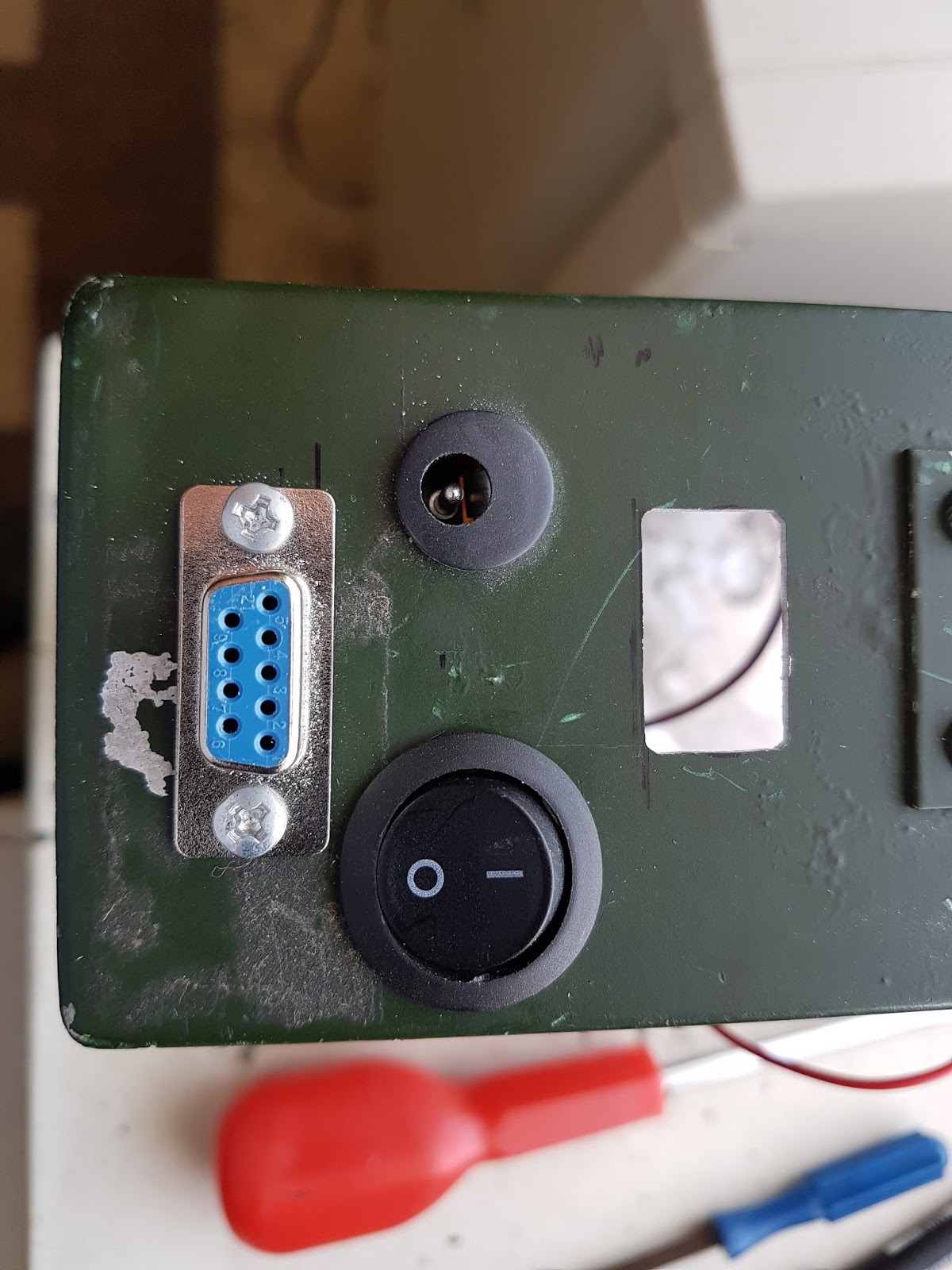 |
| Switch fitted in its 20mm hole |


Again, for very obvious reasons of there being essentially a 15V 3A 30C bomb in the box, liberal use of heatshrink was required. I also managed to wire the main switch to the battery terminals directly forgetting to fit the fuse! Another bit of corrective work and the fuse holder, plus 2A fast blow fuse, was connected The battery terminals were then reconnected, and coated in hot melt glue to insulate the screws.
A very liberal sloshing about of hot-melt glue then to secure the low voltage monitor and the USB charger modules in place.

A few bits of foam were inserted then to hold the battery in place and to stop it bouncing about in the box, and the switch, DC jack and USB output tested. So, if required, this pack can provide 5V out from the USB for general use charging phones or running small devices, and 15V up to 2A for other uses. I would anticipate that being used for devices with their own internal regulators!


As can be seen in the above photos, the low voltage monitor comes into play when the shorting plug is attached. I do still need to attach a lanyard to this to the battery case to avoid it being lost. The battery is also now marked, like the 24V LiPo pack for the PRC-320/-351, with red, in this case a band of red PVC tape around the top, to mark it out as requiring special charging.
The last thing to do was to build the balance charge cable.

With the five connections made, sleeved and tested, the D-type was fastened away in a shell. The whole pack was then put on a balance charge, ready for use.
With these two projects completed, I cleared off the bench (which by this time was a filthy mess of cut bits of wire insulation and solder blobs), and started to set up ready to do a bit more on the 4m transverter, which I have neglected for far too long.
Subscribe to:
Posts (Atom)