Wednesday, 30 September 2020

No Enthusiasm

 Ive not posted on here for quite some time. What with the Covid-19 lock-downs, the unprecidented and unbelievable scene of the control of the nations radio and TV being effected by dispersed engineer-operators working from home (myself included - I carried out one of the initial tests of the system), the travel restrictions, the cancellation of fairs, rallies, and other events, and then the sheer confusion and inconvenience of returning to working from the office....

...I just cant be bothered!

This is true, I seem to have lost all enthusiasm for not just radio and electronics, but pretty much everything other than reading and taking long baths. (this is itself is nothing unusual - ive lost interest many times before, however those times have usually coincided with life events, for instance losing interest in radio during the years I serviced public safety radio systems) The only odd thing is that this time, the loss of enthusiasm is making me anxious.

I still have many projects on the go, but I just cant bring myself to get on with any of them. I do recognise that this is a detrimental aspect of my mental health, although im rather glad that it isnt manifesting itself in the form of panic attacks! Oddly, as a result of working from home using telephony headsets and with without people close by, my telephobia has actually improved. I seem somewhat more confident and able to use the phone with less hesitation and worry, even, I feel, to perhaps having a bit of time out portable with a nice bit of HF combat net radio!

Of course, much of my current state may be attributed to the drugs im using to control other symptoms. These include some rather potent controlled substances, plus a few 'special' molecules, and are helping me overcome the insomnia, and settling down the Willis-Ekbom. Unfortunately they are also allowing me to observe and analyze life from a 3rd person perspective.


I do feel that I need to get back into some level of radio though. Not from the shack though I feel, but perhaps portable, a little SOTA maybe. Little by little myself and Bob M1BBV have managed to find slots to get a little walking in, so a few SOTA activations may be on the horizon. If nothing else, I need to get out and have some time in the wild open countryside.


I just need the motivation and inspiration to get started!


There will be more interesting posts eventually, I assure you (whoever you are, although I doubt I have many 'followers') but for now, like almost everything in life, its a case of keeping distance, and waiting.

Wednesday, 22 July 2020

No go on the 5V SLAB

Well, the SLAB that was reading 5V has definitely had it! Initially, it looked good, and I was able to transfer it to my Accucel charger. But then, the voltage started to drop, even on charge.  It was always unlikely that this one would recover.

The one reading 10V, I was much more conservative with the water (about 2ml per cell), and have left this on the slower charger. Its still only taking a very low current, just a handful of mA, but this is steadily increasing.

So, who knows?

Refurbishing dead SLABs?

I use quite a few 12V 7Ah Sealed Lead Acid batteries (SLABs), which I normally obtain as surplus due to routine replacement in UPS equipment. Recently, this source hasn't been available due to the pandemic, and I find myself with one usable battery and two dead ones.

The two dead ones are reading 5V and 10V. Shaking the one reading 5V, it audibly rattled! Clearly, it wasnt as wet in there as it should be!

So, I thought i'd try and refurbish it! The lid of these is lightly glued on, and it was fairly easy to prise it of using a sharp chisel. Under the lid, the cells are closed off using pushed on rubber caps. These easily lifted off, revealing the plates of the cells, all but dry!

As it happens, I had a bottle of de-ionised water on the shelf in the workshop. Using a syringe, ive refilled the cells up to the top, and then gently sucked the excess out of the filler holes. This proved to be a rather messy job, so a roll of paper towel was kept handy to mop up any spills and splashes.

With each cell refilled, the caps replaced, and the lid put loosely back on, it was time to try it on the charger. For this, I am using my 'semi-intelligent' SLAB charger, and monitoring the current into the battery using a multi-meter. This showed the current rapidly ramping up! Ive left it for now as the current was passing 60mA and climbing. A check of the battery voltage showed it to have risen to well over 7V at this point.

Whether the battery will recover enough to be useful, who knows. Its certainly worth a try.

Now, one thing to note - I have added more water to this first test battery than required. There is a reason for this - I dont know yet how easily the glass matting absorbs the water. It may be that it takes several hours to do so. Supposedly, the correct amount of water is just enough for the matting to appear wet.  I will top up the second battery more slowly and observe.

The first battery had dropped to about 6.5V over the 7h since I stopped charging. On restarting the charge, the current input was up at 400mA and rising. The charger can supply 1.5A. As it is now daytime and I can keep an eye on it, I will allow it to charge during the rest of the day and see how it does. For safety, it is in a plastic box and covered with paper towels.

Tuesday, 21 July 2020

Off-Grid BOINC research computer proof of concept

Quite some time ago, after a mobile phone upgrade, I hard wired a Buck converter module to the battery terminals of a Samsung Galaxy S7, removed the SIM card, and left it crunching numbers as part of the BOINC project, sat in the corner of the shack powered by the main station PSU. In its steady operating state with no display lit, it consumes about 130mA, which is probably less than the operating current consumed by the big linear PSU powering it!

My plan has always been that my main BOINC contribution should be independent of mains supply, so, after a slight debacle involving a fraudulent sale on ebay of a 100W solar panel with 30A charge controller, which when tested was shown to be a 20W panel and the controller hardly built for 10A, I have a solar panel and charge controller with which to set up a proof of concept... and half my money refunded!

The concept is simple. The BOINC phone and its Buck converter connect to the charge controller load terminals, a 12V 7Ah SLAB to the battery terminals, and the 20W panel to, well, the panel terminals of course! Unfortunately, the only battery of this size I have remaining in an operational state is the one used to power the under stairs lighting! This has been borrowed temporarily. It will be replaced for the time being with a 25Ah beast that just happens to be doing nothing.

The whole lot is in a position where it will receive a decent amount of south facing sun through the day - on my eldest boys windowsill! He wont mind - its already covered in IT and computer parts!

Some tests on the phone showed a peak current at start up of about 450mA, and a steady operational current (computing but display off) of about 130mA. This with a fully charged and 100% capacity 7Ah battery should last several days. At full sun output, the 20W panel should be capable of charging a 7Ah battery in around 5h. So in theory, this set-up should be able to operate 24/7. Of course, this battery is not new and far from peak condition!

If it operates without shutting down in the middle of the night using this battery, then I can have confidence in it operating well with a better 2nd hand unit, which I will have to scrounge up another time!

Thursday, 16 July 2020

NAVTEX Antenna repair - bypassed

The bypassing is now in place. A 100nF cap from pin 1 to pin 11 of the mixer ICs pads (remember that the IC isnt there!), this effectively connects the secondary of L3 to the supply rail. Since this system uses a combined power/signal line, that should now be feeding the receiver. A temporary link takes the other side of the secondary to ground. One leg of a 680 ohm resistor has been lifted to isolate the DC from the secondary, and a final temporary link jumps the missing L4 secondary to re-establish the DC supply to the front end transistors.

With the NAVTEX receiver in spectrum test mode, I can now see 'noise' where-as before this was totally blank, unless I put a finger on the supply wire. I can get a peak to appear on the display if I crank up a 518kHz signal from the Marconi 2955 test set. This is air coupled from a whip antenna, and had to be cranked up to about -20dBm output, but moving the antenna and its feeder around near the whip does suggest that the pick-up is by the antenna and not via the feeder or any other means. So far so good, but the proof of course will be whether it actually receives a NAVTEX transmission!

I have the station reserve receiver tuned to 518kHz as well to compare. Sadly, at the time of writing, were in a quiet part of the transmission schedules!

NASA Active Dual Channel NAVTEX Antenna Repair

Despite what the title says, its unlikely this will ever be a dual channel antenna again!

For a start, the PIC 12C508 IC, which provides the switching control and the local oscillator for the channel conversion, is not working. Whether it is just physically damaged but the code can be read, will have to be discovered. Even if the code will read, chances are that its been protected and cannot be used.

The mixer IC MC1496 has also been removed from the board. I have no easy way of testing this, so have to assume for now that it is faulty. Ive removed it to prevent any damage from causing problems with the rest of the circuit.

And so we come to L4 (as I have designated it). This is the output tuned transformer. And its knackered! I had noticed some corrosion under it, as there was with the PIC and the previously rotted off crystal. On removing it from the board I found that the fine wires of the primary had completely corroded away.

This seems at first a major problem, but in reality probably not. The frequency its tuned to is known, 518kHz, and its series capacitance also known, 150pF, so its a simple matter to calculate the secondary inductance needed, which is 630uH. Replacing it is just a matter of finding a suitable 10mm can transformer with that impedance secondary and the same winding configuration.

But for now, I have the trouble of bypassing all this to try and get the direct 'pass-through' 518kHz channel working. All the transistors tested out OK off board on their DC parameters, so hopefully its just a case of getting the supply to them and the signal from them!

The secondary of L3 is the problem. This would normally feed the mixer inputs, but also has a DC level on it for one of those input pins. So, I need to isolate that DC level from the transformer, provide a DC block from the transformer to the output/supply wire to allow the signal out, and temporarily ground the other side of the winding. I 'think' that I can isolate the DC by lifting one leg of one of the 680 ohm resistors, and a 100nF cap should work for coupling the signal.

Saturday, 11 July 2020

NAVTEX Active Antenna

Ive finally come back to the antenna for the NASA Target NAVTEX receiver.


Ive mapped out the circuit diagram, and can now start working out how to fix it.

My suspicion of the lack of 518kHz was with the transistors, but ive had them off the board today and tested, and they check out ok.

Now, I know the PIC oscillator is not working. The original crystal was corroded, so has been replaced by one close but not exactly right. I would have expected it to work but give perhaps slightly off frequencies. I suspect that at some time the antenna feed has been reverse polarised, and this has killed the chip. It might well have killed the MC1496 as well.

So, the plan now is to remove the MC1496 and the PIC 12C508 from the board, plus lift any associated components that might affect the signal path, and see if I can get it working just on 518kHz, by bypassing the conversion circuitry. Im also going to remove the transformers and test them off-board to ensure their windings are intact, as some corrosion/dirt can be seen under one of them. Testing them on board is pointless as the DC circuitry is routed through them/across their pins.

If I can get that working, then I can work on the conversion side another time. 

Monday, 13 January 2020

Nasa Marine Target Navtex Pro Plus

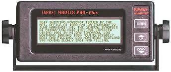
Purely because I simply wanted one, I've eventually picked up a purpose built NAVTEX receiver. This is a Target NAVTEX Pro Plus unit from Nasa Marine. Second hand, and faulty, of course!

NASA-TARGET-NAVTEX-PRO-PLUS-V2-RECEIVER

This is an older model, with external channel switching, as the people at Nasa Marine have been kind enough to supply me with a hand drawn copy of the receiver circuit diagram proving this. So the receiver itself can only handle the 518kHz broadcasts. To cope with the 490kHz National services, the active E-field probe antenna has frequency changing capability.

The receiver works - I have it connected to a short indoor length of wire, which allows it to receive some of the strongest signals. Its internal back-up battery is not in a very good way, but that's not much of a worry.

The antenna and Local/International switch box have issues. There is some corrosion on the antenna PCB - one tantalum bead capacitor has lost a leg - but it doesn't look too bad. There is a PIC micro-controller that looks to be serving as local oscillator, which has a lot of green gunk around and under it. One of the PCB traces looks rather poor as well. So long as the corrosion has not got into the transformers, repair shouldn't be too tricky. There is a destroyed track in the switch box.

So, a bit of linking out and cleaning up required!

Tuesday, 31 December 2019

XR2206 Function Generator kit, and Chinese project boxes

A number of items from the Far East have been trickling in over the holiday period, including 2N3906 PNP transistors, veroboard, audio transformers and project boxes. One such packet arrived today with five project boxes, snap-on lid types, for about £3. The quality is good, not perfect, but certainly adequate, and quite impressive for the cost! Two of these will become small Radiation detectors using the SI-19BG and the SBM-10 G-M tubes.


Another packet with two larger white boxes has also arrived. These are for the BOI-33 tube based detectors. The photo above shows the first version board fitted into the box. I need now to sort out a battery supply (waiting on coin cell holders - this will run on a 3V lithium cell), plus power switch, LED and neon indicator holes, and a sound hole for the loudspeaker, plus a row of holes along the side to allow better beta penetration to the tube.

Also for about £3 shipped, I received this little function generator kit. Actually a little smaller than I expected, the board was of reasonable quality, although the edges are a little rough, and some of the holes are a little too large.


Putting it together was very easy, although the instructions that came with it were pretty rubbish! The parts list at least was accurate.


Hard to see in the photo, but the clear acrylic case is etched with the names of the controls. The board is not bolted into the case, as the five(!) M3 nuts and bolts were too short to do so! However, the case itself is a reasonably tight fit and so there is little movement.  I've yet to test it though.

Tuesday, 24 December 2019

SBM-10 G-M tube

Yesterday I received an SBM-10 G-M tube from Russia. This tiny tube is just 6mm diameter and about 20mm long. I've tested it and it works well.

But, like the tiny SI-19BG, it has no easy way to connect to it. I'm wondering whether the socket for the SI-19BG can be made to work?

I've also realised that the voltage doubler I was working on yesterday wasn't complete! There should have been another diode, or series string. I need to test that out later.